CP5070 intro to chemical product design and development
Project Development
In this page, I will:
1. Briefly describe my team chemical device
2. Show how the team planned, allocated the tasks, and executed the project.
3. Document the entire design and build process of the chemical device and include videos, pictures, and screen captures of the processes.
4. Include “Hero shot” of every milestone of the processes, example the part A that was 3D printed, part B that was laser-cut, electronics components moved/worked according to the program. Hero-shot is taken with the person-in-charge holding/working/making the parts.
5. Include the name of the person who was in-charge of every part of the project.
6. Document my individual contribution to this project.
7. Provide the link to the page of the blog of my teammates.
8. Describe problems encountered and how the team solved them.
9. Include all the project design files as downloadable files.
10. Embed the final prototype design file, i.e., the final fusion360 design file showing the entire prototype.
11. Type my Learning reflection on the overall project development.
1. Our team Chemical Device Door Handle Steriliser
Its function is to sterilise the door handle right after someone has just grabbed the door handle to open the door. The body of our device will start at the bottom (resting position) and once the sensor detects the door handle has been touched, after 1 second the LEDs will light up and the stepper motor will rotate the body 180 degrees to the top and then back to the resting position.
Even after the pandemic, covid19 is still rampant and we do not want it to spread in social and crowded places such as offices, hence this is where our product comes in hand as most social interactions usually start off with a handshake and skin contact is the main contributor to the spread of diseases and viruses. Our device will clean the door handle each time it is being used, which prevents any transmission of diseases and viruses.


2. Team Planning, allocation, and execution
CEO (Chief excutive officer): Hai Teng
CFO (Chief financial officer): Isabella
COO (Chief operating officer): Ryan
CSO (Chief sales offcer): Fion
CRO (Chief of resources): Wayne
Click here to view the finalized BOM (BILL OF MATERIALS) table.
Click here to view the finalized Gantt chart (planned and actual) and the tasks allocation for each team member.
https://docs.google.com/spreadsheets/d/1JHsdYytnRL-4shT8Hia0wU9kRaFpwKgXBNhs9P8B-M4/edit?usp=sharing
3. Design and Build Process
Part 1. Design and Build of Main Body (done by Hai Teng and Ryan).
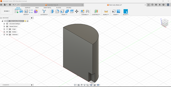
Step 1: Sketch a 60mm diameter circle and a line cutting through the middle

Step 2: Extrude a semi circle of 70mm

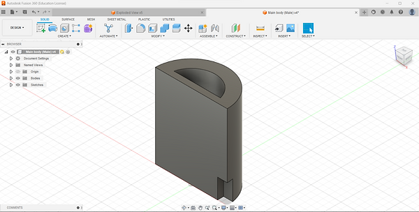
Step 3: Sketch a rectangle to put the sensor (Since this is half the body, sketch half of the sensor length and breadth (16.5mm X 8mm)

Step 4: Extrude 5mm inwards
Step 5: Sketch a 40mm circle

Step 6: Extrude 70mm

Step 7: Sketch a 40mm X 5mm rectangle

Step 8: Extrude 70mm downwards to form the base where the LED strip will be
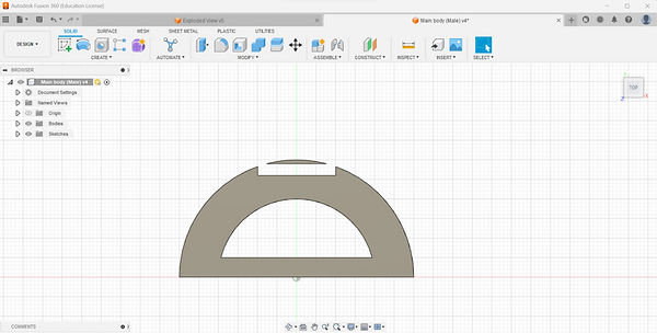
Step 9: Sketch the bottom semicircle

Step 10: Extrude 10mm downwards

Step 11: Sketch rectangles which will be the pegs connecting to the other main body

Step 12: Extrude 10 mm to create the pegs

Step 13: Create a 20mm X 3mm rectangle to put the caution sign

Step 14: Extrude 140 mm to create a space for the sign
Step 15: Sketch a 6mm circle to put the LED

Step 16: Extrude in the direction opposite of the sensor

Step 17: Sketch a rectangle to cover the semi circle on the top and extrude it 10mm inwards (This was a mistake as we wanted the wire to come out of the other side)

For Main body 2, repeat the same step and switch the sensor and LED position and extrude inwards to make holes for the pegs with 0.2mm allowance. On the other side of the body, make 3 holes with diameter of 15mm for the middle to hole the connector and 12mm for the side for wires to come out.

To print, export the drawing as an STL file and upload onto cura. Select the correct printer and desired infill. After that, slice and save to the SD card and insert onto the printer and start printing.


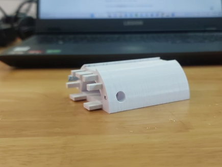

Hero Shot

Me and Hai Teng happy
Part 2. Design and Build of Wooden box, Caution Sign (done by Fion). Link it to blog: https://cp5070-2022-2b03-group4-fion.blogspot.com/p/project-development.html
Part 3. Design and Build of Clamp, Clamp Screw, Thread Connector and Thread Nut (done by Hai Teng).
Link it to blog: https://cp5070-2022-2b03-group4-haiteng.blogspot.com/p/project-development.html
Part 4. Design and Build of Gears and rack, Arm (done by Isabella). Link it to blog: https://cp5070-2022-2b03-group4-isabella.blogspot.com/2023/02/project-development.html
Part 5. Design and Build of Door Handle (done by Fion).
Link it to blog: https://cp5070-2022-2b03-group4-fion.blogspot.com/p/project-development.html
Part 6. Programming of motor and lcd (done by Isabella).
Link it to blog: https://cp5070-2022-2b03-group4-isabella.blogspot.com/2023/02/project-development.html
Part 7. Integration of all parts and electronics (done by Everyone)

First, we run the wires for the LED and sensor into the holes in the main body

Attaching the two bodies together and hole them together with the caution sign

Attach the thread connector in the hole made in the orange main body and attach the arm and nut to hole the arm in place.

Attach the other end of the arm into the stepper motor
Attach the stepper motor into the box of the clamp and secure it onto the door handle

Assemble the box together and gear together

Hang the box on our door, it stores all the wires, breadboard and arduino
4. Problems and solutions
The filament used for the body of our device broke halfway through the print, which caused the print to be incomplete. We found out from the lecturer that the filament we used was faulty, hence for the subsequent 3D prints we used a different printer and made sure the filament used was not faulty

We initially wanted to print the body of our device in one whole, when the print came out we realised that we were not able to install all the components and hide the wires well and the print that came out was incomplete with some loose ends to the design. To resolve this issue, we printed the body into two halves so that way we will be able to hide the wires easily and all the components would be easy to install.


During the laser cutting process we messed up the dimensions of our box, as it was too small to fit the breadboard and all the other components. The caution sign was too thin so the fit was not very good as it was super loose. We made the necessary changes needed and everything went according to plan.
For the Arduino portion one of the main drawbacks was that the LED light strip was 12V, however the Arduino only carries a maximum of 5V. In order to make up for this we attached the LED to a 12V battery. Next would be the coding of the LED light, instead of creating a new code for it we instead attached it to the same circuit the red LED would be in. This is due to how we initially designed it, where when the red LED turns on, the LED strip will start sterilising. This allowed us to kill two birds with one stone.
5. Project Design Files as downloadable files
-
Fusion files https://drive.google.com/drive/folders/1NjCaGLmaRZJfAz_PVdtd8ADTyl1q9KDd?usp=share_link
-
STL files: https://drive.google.com/drive/folders/1UWdlbepsevW3UF3lQ0nEmaX4owvW9aON?usp=share_link
-
.dxf files: https://drive.google.com/drive/folders/1fUyFnqGe0kWqDM21b81F83DT9_0DLWmx?usp=share_link
-
Arduino programs files: https://drive.google.com/drive/u/1/folders/1y0Xlx4osMxzrOtmaxfR5VzhVu_7ABeHR
Additional info:
Guide used to program stepper: https://docs.arduino.cc/learn/electronics/stepper-motors
Guide used to program IR sensor: https://arduinopoint.com/ir-sensor-arduino-project/
6. Below is my Learning Reflection on the overall Project Development.
I learned to push past my limits and never give up, even though there were multiple failures during the project, I kept a positive mindset and found a roundabout solution to all the obstacles that came in my face.
One thing our group should have done is made a proper prototype with the exact dimensions of our real device as this would have allowed us to not face as many problems as we did.
Overall, I really enjoyed building the Door Handle Steriliser as I was able to bond with my teammates and I got to use the laser cutter again. I also felt that my 3D printing skills improved as compared to last time. I would 100 percent do this again and I cannot wait for my Final Year Project (FYP) next semester as it is very similar in certain aspects as this module.
End Result